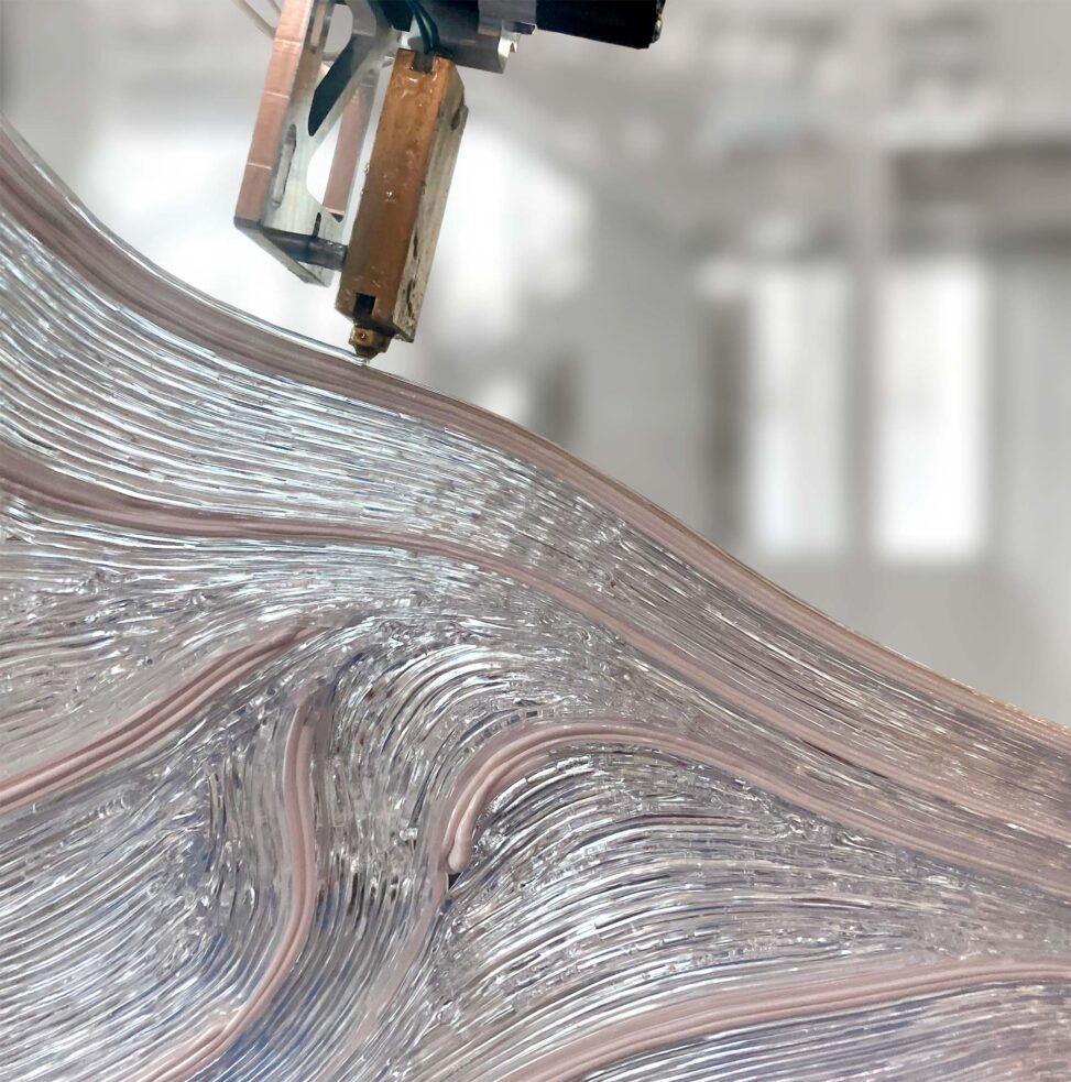
How can we approximate a shape using non-planar paths that conform to its geometric features?
This work continues the research on the development of computational techniques to design non-planar print paths for robotic 3D printing. We control the paths using a parametrization function that is defined considering a tangent guiding vector field as its gradient. This provides more flexibility in the possible input constraints compared to the recently published boundary-controlled method.
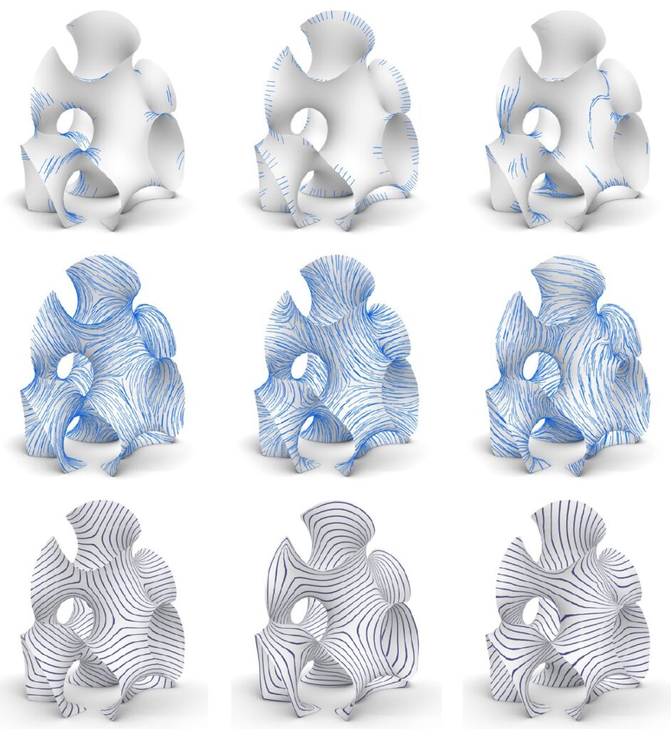
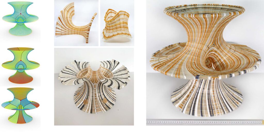
We optimize the governing vector field considering properties desirable for fabrication, such as alignment to user-defined directions, smoothness, unit length, and integrability. The illustration below shows the resulting parametrization function controlled by a vector field aligned with principal curvature directions (left), boundaries (middle), and user-drawn directions (right)
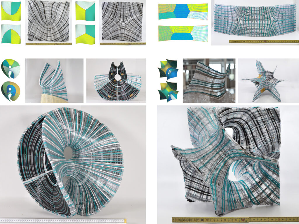
In addition, we optimize a second vector field orthogonal to the original field to create a 2D parametrization that can be integrated into two orthogonal strip networks that, when overlayed, form a strip-decomposable quad mesh.
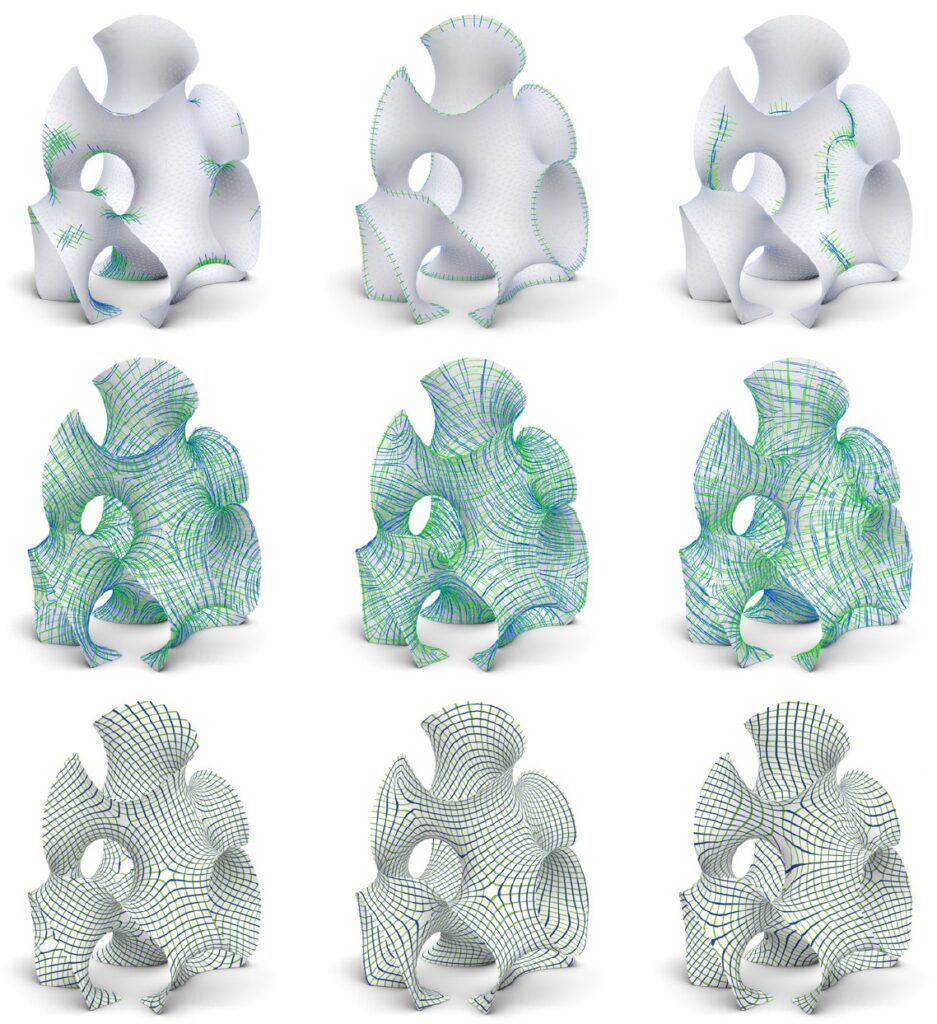
This discrete quad mesh representation is very handy for fabrication, as it can be used to edit the produced paths, partition them into singularity-free patches that can be fabricated in one go, and add fabrication details such as rigidifying ribs.
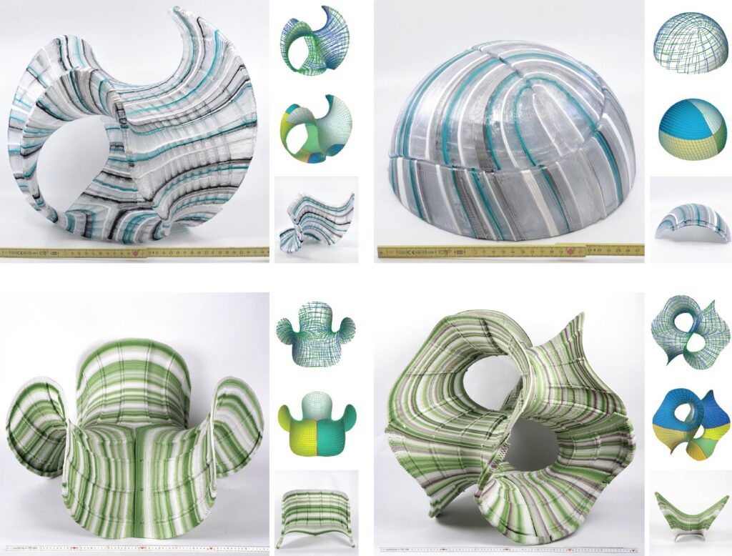
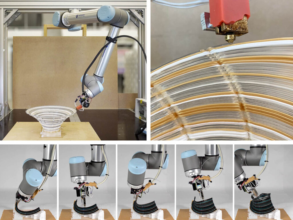
In addition, we can use the information from the two vector fields to print double-shell geometries with transversal path orientations on each side. This adds structural depth to the resulting object, thus improving stability. It also allows distributing imperfections more evenly along different directions on each side of the shell.
The video below shows the entire process of creating a double shell print.
Acknowledgments
This research has been part of my doctoral research titled Nonplanar Layered Morphologies at ETH Zurich, at the Institute of Technology in Architecture, chair of Digital Building Technologies, under the supervision of Prof. Benjamin Dillenburger.
Additional advisors: Olga Diamanti, and Amir Vaxman.
The outcomes of this research have been summarized in the following publications.
Mitropoulou I., Vaxman A., Diamanti O., Dillenburger B., 2023. Fabrication-Aware Strip-Decomposable Quadrilateral Meshes. In: Computer Aided Design journal, Elsevier.
Mitropoulou I., Vaxman A., Diamanti O., Dillenburger B., 2023. Non-planar 3D Printing of Double Shells. In: RobArch 2024. In review process.